While maritime transport contributes 2.2% to global emissions, significant adoption of LNG as a marine fuel will support global efforts to reduce emissions. And for the LNG industry itself that use could provide a significant incremental source of demand.
The International Maritime Organisation (“IMO”) plays a key role in regulating the maritime sector alongside national agencies and local authorities. Various rules and regulations are in force with the aim of tightening emissions controls.
With these goals in mind, LNG can deliver a significant reduction in emissions and is being viewed as an increasingly attractive option across the marine fuel value chain. A relatively small number of vessels currently operate on LNG, or as dual/tri-fuel with diesel electric propulsion. But a growing number of vessels are being ordered and more than 50 ports globally have or are preparing for LNG bunkering.
Significant adoption of LNG for bunkering requires positive steps on both the demand and supply side. For the former, there is the cost of retrofitting or choosing propulsion that utilises LNG; and for the latter, the installation of LNG bunkering facilities.
Scale and supply chain issues will impact how LNG is bunkered – truck to ship, shore to ship, ship to ship, or portable container to ship.
The majority of bunkering facilities today are in Europe, with Norway leading, but the EU is supporting further developments. In Asia, China leads the way, with emissions regulations promoting the development of facilities both inland and coastally, while Japan, Korea and Singapore have or are developing LNG bunkering.
Boil off gas is generated from LNG which needs to be treated so as to avoid pressure build up. Various options exist, including liquefaction (mixed refrigerant or turbo expander that depend on scale), using the gas for fuel either onboard or shore side; keeping in small pressured tanks which circumvent the need for treatment over a short period of time; and feeding the gas into the grid.
A number of factors combine to determine how to optimise an LNG bunkering facility: these are scale (potential volumes required), infrastructure (any constraints) and logistics (delivering LNG to the facility and to the vessels seeking to bunker LNG).
This article is a summary of a more complete report that Enerdata has just released called LNG Bunkering Market Overview, where much more information is available. Please contact us for more information.
Introduction to Ship Bunkering
With legislation mandating a reduction in emissions as well as restricting the sulphur content of fuels, ships can take various measures:
- Scrubbers – installation is effectively on the existing exhaust stack but can result on a 1-3 percent increase in fuel consumption. Easy to apply to existing vessels.
- Marine Diesel Oil (“MDO”) – “cleaner burning” than heavy fuel oil “(HFO”), but more expensive than HFO.
- LNG – = much lower emissions than oil based fuels, but takes up more space than a conventional propulsion system, and reliant on ports having fuel available.
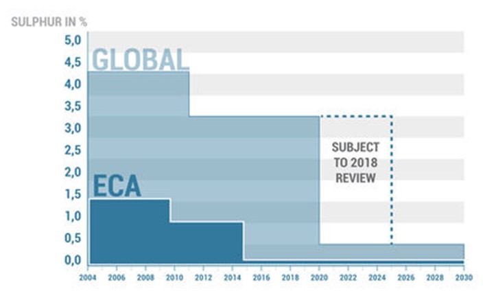
HFO consumption in bunkering has been declining since 2011, this being more pronounced in Europe than Asia, with the former having designated emission control areas (ECAs) where the magnitude and timing of reductions are being accelerated.
Figure 1: Sulphur Emissions
The economics of LNG over oil based fuels will depend on the price spread.
LNG Bunkering Models
A number of factors influence the way in which bunkering can take place, including the scale of operations and infrastructure. Four models can be identified.
- Truck to Ship
Truck to Ship bunkering is most often carried out from a tanker, which connects using flexible hoses.
The advantages are (i) location flexibility: the LNG truck can easily travel from the liquefaction point to a remote location to fuel the ship and (ii) the relatively low investment needed relative to the other methods.
The disadvantages are (i) limited capacity: trucks are typically 48,000 to 60,000 litres; and (ii) comparatively low transfers rate compared to the other bunkering solutions, thereby effectively ruling out this option for large vessels.
- Shore to Ship
In Shore to Ship bunkering, LNG is transferred to the ship by connecting flexible hoses to a fixed on-shore storage tank near the jetty.
The advantages are (i) high scalability as the size of storage can be increased easily and (ii) location flexibility with LNG supplied via LNG trucks or a small scale liquefaction facility.
The disadvantage is that the location is fixed.
- Ship to Ship (in port or at sea)
One LNG vessel is used to transfer LNG to a second. The vessel carrying LNG is loaded at a liquefaction terminal, a storage facility or from LNG trucks at a port. The vessel will then travel to the location of the vessel which needs LNG as fuel.
The advantages are (i) location flexibility (ii) rapid fuel transfer rate and (iii) the ability to transfer large volumes of LNG.
The disadvantages are (i) that offshore operations may be affected by adverse weather and (ii) the capital investment may be significant.
- Portable tank transfer
A mobile tank (container) is used and can be brought on board the ship to supply LNG as fuel. Alternatively, LNG can be directly transferred from the tank to ship at the port.
The advantage is the flexibility afforded by the tank that can be taken on and off a ship and refilled.
The disadvantages are (i) physical transfer from port to ship; (ii) the need to connect and disconnect the tank to provide fuel; and (iii) relatively low volumes.
Current Status of LNG Bunkering Facilities
Primarily as a result Norway’s drive to reduce emissions, Europe accounts for 86 percent of ships that are LNG fueled by number, the Americas 8 percent and Asia 6 percent.
- Europe
The principal facilities are located in Belgium, France, Norway, Spain, Sweden and the Netherlands. In scale they vary from, for example, the Gasnor facility in Bergen which has 500 cubic meters (cu.m) of storage, through to Montoir, which can bunker from its LNG receiving terminal at 4,000 m3/hour.
With the European Union (“EU”) policy of at least one bunkering facility in each member state, and funding programs in place, numerous other facilities are planned.
- Asia
China has established several bunkering facilities with others under development, primarily as a result of regulations seeking to limit emissions both on inland waterways and in three designated coastal zones. Inland, along the Yangtze River, facilities are currently operational at Chongqing, Yidu, Wuhu and Nanjing.
in Korea, bunkering facilities are in place at the port of Incheon and the aim is to develop facilities at Busan by 2020. Japan and Singapore also have plans for facilities.
- Americas
Few facilities currently exist in the Americas. A small facility operates in Argentina with a company operating a plant to fuel its own vessel, while in the USA separate facilities are operational at Port Fourchon and Jacksonville.
In the US, facilities area also under development in Los Angeles while others are likely to emerge in the Seattle-Tacoma area and New York. In Canada, probable ports for the development of LNG bunkering include Tadoussac and Vancouver.
Small Scale Bunkering Facilities: Operational Procedures
Small scale LNG can be classed as liquefaction facilities with aggregate capacity less than one million tons per annum. “Small” scale storage facilities (land or sea) would be in excess of 500 m3 and up to 30,000 m3.
Broadly speaking small scale liquefaction plants have a wider range of technology choices and while people tend to think of the scale of global export facilities, many smaller plants exist serving local markets.
- Land Based Storage
The containment systems involved in LNG storage reflect scale and the extent and way in which boil off gas (“BOG”) will be treated. There will also be a trade off in balancing insulation and the pressure the tanks can be subjected to.
At atmospheric pressure, smaller scale facilities are more likely to be single containment systems, progressing in scale to double containment and then fully insulated. Tanks that are pressurised will generally store much smaller LNG volumes than those which are used at atmospheric pressure.
- Floating Storage
For some time, purpose built or converted LNG vessels have been used as floating storage regasification units (“FSRU”) either delivering directly to shore or having receiving cargoes via ship to ship transfer. Ship to ship transfer can also be used for onward coastal shipments from large vessels.
Thus the operating principle of using a vessel for LNG bunkering is well established, and can offer both operational flexibility and the ability to circumvent the need for significant shore based infrastructure.
- LNG transfers
In any LNG bunkering operation, the environment will be dynamic, with one or both entities in a waterborne environment.
For ship to ship transfers cryogenic hoses are utilised, able to achieve rates up to 1,500 m3 an hour, operating in ambient temperatures with LNG and pressures up to 20 bar.
Figure 2: Ship To Ship Transfer – Key Operational Steps (Courtesy: Bmt)
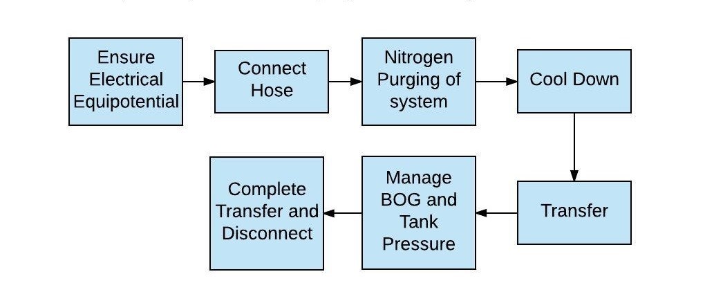
Loading arms which are shore based have less operational flexibility but can achieve higher flow rates, up to 10,000 m3 per hour.
Flexible cryogenic hoses fit small scale operations, such as truck to ship transfers, in part due to the lower volumes and therefore flow rates required, but also because of the higher stresses to which the hoses are subjected.
LNG carriers in short haul and coastal trades might typically range from 1,000 m3 to 20,000 m3 and are operationally well established. Vessels for bunkering are a more recent addition to the scene, examples of which are shown in Table 1.
Table 1: Examples of LNG vessels ordered for bunkering
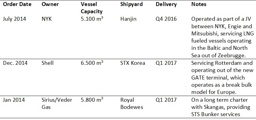
Source: Enerdata World LNG Database
LNG trucking involves small volumes, typically 20-50 m3, with a need to cool down the truck in order to avoid excessive BOG during loading. When unloading the risks to be mitigated will include limiting BOG and ensuring there is no LNG spillage.
Boil Off Gas Treatment
With LNG having to be kept below minus 163 degrees centigrade, BOG generated as a result of heat ingress and kinetic energy (motion) has to be treated to avoid a pressure build up, given the six-hundred-fold expansion that takes place in the transfer from liquid to gaseous phase. BOG can be dealt with in one of three ways.
- Re-liquefaction
Cooling the BOG will allow it to liquefy again and is achieved in one of two ways: liquid refrigerants or gas turbo expanders.
In the former a mix of refrigerants is used, whose compression and expansion causes the cooling to take place. This method is relatively high in capital but low in operating cost and start up is complex. Hence it is unlikely to be restricted to shore.
In the latter, methane and nitrogen are usually fed through turbo expanders which also case the temperature drop. These facilities are quick to start up, and do not require a complex refrigerant handling process, but their limitation is in being small scale.
- Containment
Relatively small tanks, of say 7,000 m3 designed to withstand a 30 bar pressure, can be filled with about 90 percent liquid, the balance being vapour, and with boil off at 0.2 %/day are good for about 2.5 days.
The pressure build up can be used to discharge the LNG and hence these tanks can be used for a small vessel travelling over a relatively short distance (e.g. at 15 knots, cover 900 km in that time period) with the need for BOG treatment.
- Using the boil off gas
Due to the high methane content of BOG, an LNG carrier of 10-20,000 m3 is able to utilise this for fuel without pressure build up. It can additionally be used for on board heat and power, or to provide fuel for terminal operations.
Larger vessels, or storage facilities usually require additional handling, for example, the gas being compressed and comprising part of the send out volumes to the grid, or having to be liquefied again and returned to the storage tanks.
Sizing a Bunkering Facility
Three primary factors determine the scope and scale of a bunkering facility.
- LNG Bunkering Demand
This can be taken as effectively the number of reloads, the volume required and the frequency of port calls. For the purpose of managing bunkering, a “liner” type service will be most amenable given the relatively certainty this brings.
The principal uncertainty would arise from any potential change in trade patterns, of if vessels were, for example, dual fuel, variation in demand from inter fuel competition.
- Infrastructure
Generally speaking, the size and scale of facilities should reflect potential demand, but given such facilities are likely to be developed at existing ports, availability of land, as well as issues such as permitting and a reliable supply chain can all impact on the way in which facilities may develop.
- Logistics
This impacts both the sourcing of LNG (e.g. a regasification terminal, or from an existing land based facility) as well as the delivery of LNG (e.g. any port constraints, or vulnerability to weather).